 Now it took me a long time to get used to repair information on computer and I held on to the books as long as I could but the time came long ago that electronic repair information is more cost effective and practical. That being said, we'll pull up an Alldata diagnostic chart as well.
http://www.screencast.com/users/Styxxed/folders/Default/media/6c1035bc-db97-412f-90b5-f46efb5678ea
If we start with the Mitchell chart we'll see a suggestion to look the system over under the hood. Inspect vacuum hoses, plug wires and connections. Not a bad idea but the car was sitting here running fine until it cut out and stalled. So I'm not going to spend a lot of time looking for broken vacuum hoses or leaky plug wires. Checking connectors is good but I'm not going to get deep into that either. Initially we want to get right to the heart of the matter and if I'm not getting spark or fuel because of a bad connection it will show up later too. A quick once over and those things look good enough to me. Next is to remove the plugs for inspection. Well I'm not going to do that at this point either. If I have spark to the plugs at the wires, fuel pressure to the rail and injector signal then it would make more sense to pull the plugs and look for fouling preventing them from firing. But again, the car was running and did not flood out. It just stalled suddenly so we'll skip the plug removal. As long as we are aware of what steps we are performing and what we aren't, as long as we continue in a logical approach and step by step, we'll get some useful testing done. Notice how the testing tree does teach a logical approach, even if we aren't using every suggestion as presented. It says look for obvious problems, then begin ignition system inspection with the spark plugs. Instead of plugs we'll look for ignition spark at the wires. I'm going to take a simple adjustable spark tester, open the gap wide so that I know there is plenty of power in the spark and run a plug wire to the tester.
 When I crank the engine I see a good spark across that gap. For now, I'm finished checking the ignition system. It gets a tentative pass from me. Bear in mind that for all we know that one coil tower is the only one on the car firing. The repair manual suggests looking for spark at each coil but we are not going to do that. I still want to know if I have fuel delivery. Let's don't get tied down to one aspect of things until we have a good overview. It isn't difficult to test fuel pressure on this car. There is a schrader valve in the fuel rail and my pressure gauge has a fitting made to fasten to that valve. It is more convenient though to put a noid light in an injector connector and see if I have injector signal. I'll save the fuel pressure test for later. When I crank the engine and see no flashing noid light I have found where to start sinking my teeth.
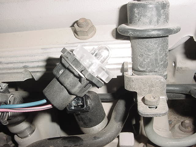
The OTC/Mitchell manual has pointed through ignition testing first and though we made adjustments to that trouble tree we are now at the point to begin fuel system tests. The Alldata chart just happens to begin with injector noid light testing so we can go to that one for a bit. Since we have no flash from the noid light we need to see if we have power to the pink/black wire. This same wire powers the ignition module and we do have spark but according to the wiring diagram the ignition feed could be good and a problem further down the circuit still keep the injectors from receiving power. A test lamp at the injector connector is what I use. A meter would show if there was voltage but a test lamp will pull current to light the bulb. The current draw can show a poor connection where a meter would not. Anyway, this circuit looks to be good. That means we have no flashing noid light because of a problem on the ground side of the injector circuit. Ground is provided to the injectors by the engine computer and pulsed according to the amount of "on" time the computer determines is needed. At this point our Alldata tree suggests to remove the connector from the ignition module and to test for power on the pink/black wire. We can skip that because the car has ignition spark and since the pink/black wire is the ignition power wire it must have power.


You can disconnect the module connector, take a test light lead and connect to the positive battery post, touch the probe tip to the purple/white wire at pin c and simulate the signal closely enough that the computer thinks it is the same thing. The ecm is just looking for a signal voltage. It has no idea where it came from.

I just find that interesting. Comes in handy at times as well. You can use that same method to simulate a pickup coil signal to the module in an old HEI distributor system.
Back to the problem at hand. We want to know that the wires from the injectors to the ecm are good. These injectors are bank fired. One bank is triggered by the dark blue wire at ecm pin C11. The other by dark green at pin C12. Since we have power to the injectors on the pink/black wire with the key on then all we have to do to see that the wiring is intact to the ecm is to use the test light at C11 and C12 to verify the circuit. The lamp should light. It does. At this point the Alldata tree suggests replacing the ecm. Before doing that I would suggest testing ecm powers and grounds. Another glaring hole for me is that I have not looked at sensor datastream or engine codes. It is very possible for a sensor to cause no injector pulse as part of a programming design. For instance, a throttle position signal that indicates full open throttle on crank and the car will go into clear flood mode with no injector signal. A coolant temperature signal that indicates extremely hot conditions can cause the ecm to lean the fuel mix so much that there is little or no injector signal. Now every computer circuit can be tested at the ecm with a scope or meter but it is time consuming and what you really want to know here won't be found that way. What you want to know falls into the strength area of a scan tool. You want to know what the ecm thinks the sensor data is, what it thinks the voltages are on its connector circuits. That tps signal could be perfectly normal tested with a meter but it is possible for the ecm to be misreading the signal and that is what you can see with a scan tool datastream. So before replacing this ecm we'll look at powers, grounds, datastream and codes. One more thing, we need to test the resistance of the injectors while the no-start is present. A shorted injector could shut down the driver circuit.
I don't see any problems so we'll do the ecm swap. It is fairly simple. The ecm is behind the glove box but I already have it out for testing access. Just disconnect the wiring, remove the access cover. You need to remove the PROM from the old ecm and put it into the new. It contains the programming information for the particular car.


Now back in the olden days (heh, heh), I would check the PROM for available updates. We had no flash PROM then. Read the scan tool PROM ID or use the physical number on the PROM and check in the manual. AXAU 9718 is the PROM number and is the latest update for this application. Good thing because I doubt new PROMs for these old cars are still available.
I got the ecm connected and the car cranked right up. Just button it all up and we're done. Thanks for reading and hanging out with me. I hope you learned that even though we made modifications to the published diagnostic procedures and streamlined things a bit to get a result quicker, we were still doing the same thing. Following a trouble tree of our own design to approach the problem in a logical manner. That's what it is all about.
Kenneth Hayes
AKA Deranger