Engine replaced with used. No start after engine replacement. Customer suspects bad computer.
I saw the spare parts in the back of the truck. Looks like there was some difference in engines and the intake manifold was swapped out as well. You can get into trouble swapping year model engines on a Dodge if you don't keep the original flywheel with the engine that is installed. The crank sensor is triggered by the flywheel and they are not all the same. I even had one in with a miss after an engine swap that turned out to have the 3.9 v-6 flywheel behind a v-8. But since the flywheel was gone from this old engine I assumed it was the one installed.

The engine cranked well but no start. No hit, no backfire. Just spun over. Usually at this point I would check for spark and fuel but I was more than a bit curious why the customer blamed the computer. I decided to use a scan tool first and see what sort of information I could find. The scan tool could not establish communication with the pcm. At the diagnostic connector, where the scan tool connects to the vehicle, you need to have a ground on pin 4 and power on pin 16
or you will have no communication with the scan tool. Some scan tools will power up automatically once plugged into a data link connector if the ground and power are good on those two pins. If you are using one of the scan tools that does that and you connect but don't see it power up then you have a pretty safe bet you are missing a ground or power. In this case I was using a scan tool that does not power up automatically. But if the fault was with the data link connector I would have no communication with any of the modules. I had no communication with engine or transmission which are both functions of the pcm. I also tried OBDII communication. Sometimes you will find a pcm or ecm that will not communicate from the OEM side but still work when queried as OBDII. Not this one though.
I did get communication with ABS, Body and Airbag modules. The ABS had stored a code for mismatched vin. I usually see that after someone has tried a used pcm. The ABS module noticed the vin from the borrowed pcm didn't match the vin stored in memory and sets the code. No other codes but a "no bus" message on the instrument panels mileage display. You'll see "no bus" when there is a module communication problem. With a mental note of the message and the ABS code, I decided to check power to the pcm. The pcm gets fused battery power at pin 22 of the C1 connector. I like to remove the cover from a connector and be able to see the wires actually at the point they enter. I can verify the pin 22 wire is actually the red/white that my wiring information says and I can see if there is corrosion or damage in that area. I just feel better when all the bases are covered during a test so that I can have confidence in the results.

I found no problems with the connector, wire or pins and verified battery power present. I used a standard test light because in a case like this I want a load on the circuit during the check. The next step, to me, was to check that I had 5 volt reference from the pcm. If there is no reference voltage then there is no communication. The violet/white wire on that same connector, at pin 17 supplies 5 volts to several key sensors. The easiest place to test for the 5 volts is at the throttle position sensor connector. No test light this time but a digital meter. No voltage on the violet/white wire with key on and sensor connected. A sensor can short internally and kill the 5 volt supply so I tested again with the tps disconnected. Still no voltage.
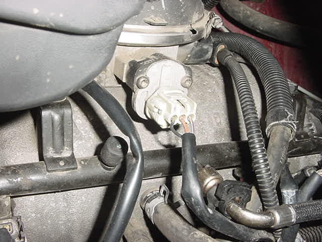
I had already disconnected the throttle position sensor and it wasn't that. It wasn't the cam position sensor. I disconnected the crank position sensor and BINGO! Five volt supply returned. The harness for that sensor runs right along the top of the bell housing. A likely spot to get a wire pinched between the engine and transmission.
I couldn't see in that area very well. I did get my hand in there and could pull no slack in the sensor harness. I snaked a borescope lead down there and it did appear to be damaged.
 You see how those wires go under the bracket and disappear? A little more effort and I got an angle on the point they re-appear from between the engine and bell housing. Very definitely those wires were caught in a bad spot and shorted to ground.
 I removed the torque converter, starter and bell housing bolts. Removed the old sensor.

With everything bolted back up and a new crank position sensor installed everything was fine.
Kenneth Hayes
aka Deranger